The technological breakthroughs in the field of power electronics have transformed the automotive, military, and defense industries. Particularly, the reliance of the aerospace industry on electronic systems has increased significantly. To keep up with the aerospace industry's requirement of high power densities, electronic manufacturers' job has become more challenging.
The increasing operational voltages impose electrical stress on the printed circuit boards (PCBs) and make them vulnerable to partial discharges (PD) and dielectric breakdown in extreme cases. Conformal coating is applied to protect PCBs from such damages and for increased dielectric strength, protection, and reliability. To prevent degradation of this coating under harsh environmental conditions, the coating must have sufficient thickness.
This article analyzes the causes of partial discharge in PCB insulations (in the aerospace industry) while they adhere to high operational voltages. Moreover, some methods to prevent partial discharge in PCBs are discussed. Finally, some products from Techspray are highlighted to assist the engineers in the PCB manufacturing process.
Aircraft Electronics (a.k.a. Avionics)
The advancement in the field of power electronics has made modern aircraft electrical machines. Electrical systems have replaced aircrafts’ conventional pneumatic and mechanical counterparts. For example, electrical actuators have replaced pneumatic and mechanical actuators. This has led to a decrease in fuel consumption, overall weight, and maintenance costs.
However, to meet the requirement of high power density in IPC class 3 PCBs of aircraft, the operating voltages have increased considerably instead of deploying high current rated conductors. In modern aircraft such as the Boeing 787 Dreamliner, the operational range of voltage has risen from 115 V AC to 230 V AC and from 28 V DC to ±270 V DC [1]. Conformal coatings are applied to the PCBs in the aerospace industry to prevent them from the harsh environment (pollution, temperature, pressure) while ensuring high dielectric strength. The performance of these coatings depends on:
- Operating temperature
- Operating pressure
- Operating voltage (amplitude and frequency)
- PCB Cleanliness
What Is Partial Discharge?
As per the IEC60270 standard, partial discharge (PD) is a localized electrical discharge that does not completely bridge the insulation between conductors [2]. PD occurs because of electrical stress in the insulated area between the two live traces when the operating voltages are high enough. PD occurs when the electric field exceeds the dielectric strength of PCB insulation.
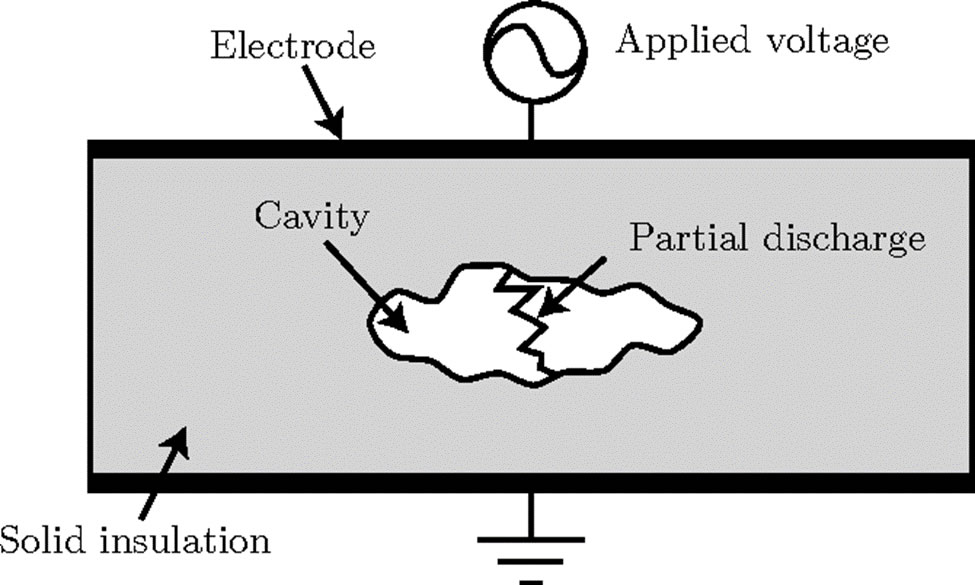
Figure 1: Partial Discharge explained pictorially [3]
The lowest voltage at which PD occurs is termed the inception voltage. PD is known to cause degradation in PCB insulation/coating due to the high electric field associated with the phenomena. Note that once PD occurs, it keeps on occurring. This continuous occurrence of partial discharge may lead to a complete dielectric breakdown of the insulation protecting the PCB, thus posing serious risks to the lifetime of PCB insulation and system integrity.
The PCBs in the aerospace industry are more vulnerable to PD owing to the harsh environmental conditions. The exposure to pollutants harms insulation resistance and it accelerates the aging process of the coating. Moreover, at very high altitudes (greater than 15,000 meters), the temperature can fall below -50oC and pressure as low as 1.68 psi. Low pressure greatly reduces the inception voltage and increases the probability of partial discharge [4].
Case Study: Reducing Partial Discharge
Cleaning the PCB before applying the conformal coating is the first step to reducing PD. A PCB with no solder or flux residues is the least sensitive to PD damage compared to its contaminated counterpart. Once the method of coating application (manual spraying, automated spraying, or dipping) is selected, the next important task is to identify the coating nominal thickness.
One case study [4], aims to investigate the nominal thickness of the coating that protects the PCB from PD under environmental conditions in the aerospace industry. The test substrate was made from FR4 material with copper traces covered by a solder mask except in the narrowest region as shown in Figure 2.
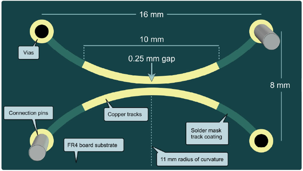
Figure 2: Test board [5]
Before coating, the boards were thoroughly cleaned in an ultrasonic bath to remove leftover residues and contamination. The silicone-coated boards were placed in a chamber and an electrical signal with the following specifications was used to energize them:
- Test Signal: Sinusoidal
- Frequency: 50 Hz
- Voltage step: 100 V/s
The temperature and pressure inside the chamber were varied in accordance with the requirements of the aerospace industry. The boards were powered for 9600 minutes or until the occurrence of PD (whichever happens first). Ten boards were selected for experimentation with varying coating thicknesses ranging from 3.94 to 7.87 mils. Inception voltage at ambient pressure was noted at 4500 V [5].
Moreover, the inception voltage was found to be decreasing with the decreasing pressure i.e., from 4000 V at 7.25 psi to 1700 V at 1.68 psi. It was noted that thin coatings were more sensitive to damage from PD as compared to thicker coatings. In a study in [5], it has been experimentally proved that not only the thin silicone coatings experience damage, but thin acrylic and parylene coatings are similarly sensitive to PD damage.
The temperature was found to be directly proportional to the damage rate [4]. As compared to no damage observed at -55oC, considerable damage (surface cracks) was observed at 70oC after 69 hours of testing as shown in Figure 3. These cracks are responsible for increasing the electric field on surfaces and reducing the inception voltage.
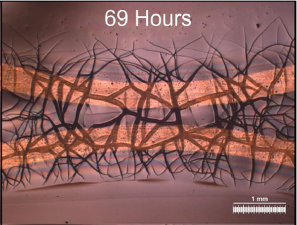
Figure 3: Cracks appearing in a 135 um thick silicone coated PCB at 70 degrees [4]
Higher temperatures increase the energy carried by partial discharge electrons. High temperature and low pressure simultaneously cause a decrease in relative air density which contributes to increasing the energy of partial discharge electrons [4]. The coating thickness of 7.87 mils or more seems to provide maximum protection at voltages greater than inception voltage and under varying environmental conditions related to the aerospace industry. The summary of test results on a 7.87 mil thick-coated board is shown in Table 1. An important point to keep in mind here is that all voltages listed in Table 1 are above the inception voltage. The quality of silicone coatings used in this case study can be assessed from the fact that none of the silicone coatings broke down at the lowest test pressure and highest test temperature value despite extensive damage.
| Ser. |
Pressure (psi) |
Temperature (oC) |
Voltage (kV) |
No degradation electric field (KV/mm) |
|
1 |
7.25 |
20 |
4 |
5.5 |
|
2 |
1.68 |
20 |
1.7 |
2.3 |
|
3 |
14.5 |
-55 |
5.5 |
7.5 |
|
4 |
14.5 |
70 |
6 |
8.3 |
Table 1: Peak surface electric fields of a 9.84 mil thick silicone coated PCB
Techspray’s Line of Conformal Coatings
Being the industry-leading player since 1968, Techspray offers an extended line of conformal coatings to its clients. Techspray offers Acrylic Resin, Silicone Resin, and Urethane Resin conformal coatings that are IPC CC 830B and UL94-0 qualified. Among all conformal coatings, Fine-L-Kote SR Silicone Conformal Coating (UL746E certified) and Fine-L-Kote AR Acrylic Conformal Coating provide the highest dielectric strength of 43 kV/mm and 25 kV/mm respectively. They are best suited to harsh environments like the aerospace industry which have high voltages at the low pressures.
References
|
[1] |
E. Zeynali, R. Bridges and B. Kordi, "Investigation of Partial Discharge in Aircraft Conformally-Coated Printed Circuit Boards," in 2019 IEEE Electrical Insulation Conference (EIC), Calgary, AB, Canada, 2019. |
|
[2] |
I. E. Commission, "High-voltage test techniques - Partial discharge measurements," 2015. |
|
[3] |
E. H. S. E. P. R. Vaibhav Patil, "PARTIAL DISCHARGE MEASUREMENT ANALYSIS ON RING MAIN UNIT," IJARIIE, vol. 2, no. 3, pp. 4130-4140, 2016. |
|
[4] |
C. Emersic, R. Lowndes, I. Cotton, S. Rowland and R. Freer, "The effects of pressure and temperature on partial discharge degradation of silicone conformai coatings," IEEE Transactions on Dielectrics and Electrical Insulation, vol. 24, no. 5, pp. 2986 - 2994, 2017. |
|
[5] |
C. Emersic, R. Lowndes, I. Cotton, S. Rowland and R. Freer, "Degradation of conformal coatings on printed circuit boards due to partial discharge," IEEE Transactions on Dielectrics and Electrical Insulation, vol. 23, no. 4, pp. 2232 - 2240, 2016. |